![]()

|
FireDot.com |
![]()
2. Solenoid Monitor When Used As A Reset Relay
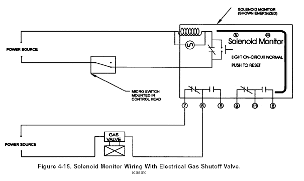
The Model SM-24/120 can be used as a reset relay when required. A reset relay is required whenever an electrical gas shut-off valve is used in conjunction with the Pyro-Chem Kitchen Knight II Restaurant Fire Suppression System. For typical wiring connections. See Figure 4-15.

REMOTE PULL STATION INSTALLATION
The Model RPS-M Remote Mechanical Pull Station is used for remote mechanical actuation of all systems releasing devices. It is to be located near an exit in the path of egress from the hazard area no more than 5 feet above the floor.
NOTE: A Model RPS-M Remote Mechanical Pull Station must be used for manual activation of a Model EN-MCU3 or a Model NMCH3 releasing device.
The Pull Station can be surface mounted or flush mounted. For flush mounting a RACO#232 4 in. (10 cm) deep electrical box or equivalent must be used (dealer supplied). It is connected to the releasing devices using 1/16 in. (.16 cm) diameter stainless steel cable. The cable enters the pull station box through the center hole in the bottom, top, either side, or the center back hole. The cable enters the control side, or the center back hole. The cable enters he control head through the top-center knockout. The cable must be enclosed in 1/2 in. (1.3 cm) conduit with a Pyro-Chem Kitchen Knight II corner pulley at each change in conduit direction. Maximum limitations for the Model RPS-M Remote Mechanical Pull Station are a follows:
Model RPS-M Cable Run Limitations When Used with Model ECH3, MCH3, EN-MCU3, and NMCH3 Control Heads and CBP-1, SBP-1, and WBP-1 Pulley Elbows
Maximum length of
cable:
150 ft. (45.7 cm)
Maximum # of pulleys
(1/16"):
40
After mounting the pull station box and conduit, feed the stainless steel cable from the releasing device, through the conduit, and into the pull station box. Feed the cable through the brushing and through the hole provided in the pull handle. Look the cable through the pull handle and secure it with the crimp provided (see Figure 4-16).

Cut and thread the cable through the hole in the latching arm of the control head and pull the cable tight. Crimp the cable approximately ten (25 cm) to twelve inches (31 cm) below the latching arm. Note: NFPA-17A requires the pull strength to be no more than 14 in. (36 cm).
NOTE: Crimps must always be used in conjunction with two (2) cable lengths. Loops are the accepted method of connecting the cable to mechanical components. The crimp must never be used on a single cable.
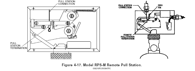
Pull the pull handle until the crimp touches the latching arm. See Figure 4-17. Coil the excess cable in the pull box and attach the cover plate with the four screws provided. Insert the pull handle into the cover plate and insert the plastic break rod.
